If you want to learn what is routing protocols so should know the Basics Of NETWORKING.
What is a Computer Network?
A network is a collection of computers, printers, routers, switches, and other devices that are able to communicate with each other over some transmission media.

Types of Networks
- There are two basic types of networks currently in existence:
- A Local Area Network (LAN)
- A Wide Area Network (WAN)
Local Area Networks (LAN)
A Local Area Network (LAN) is a group of computers and network communication devices within a limited geographic area, such as an office building. No third party involvement here.They are characterized by the following:
- High data transfer speeds
- Generally less expensive technologies
- Limited geographic area
Wide Area Networks (WAN
A Wide Area Network (WAN) interconnects LANs It is not restricted to a particular geographic area and maybe interconnected around the world. A third-party network is involved.They are characterized by the following:
- Multiple interconnected LANs
- Generally more expensive technology
- More sophisticated to implement than LANs
- Exist in an unlimited geographic area
- Less error resistance due to transmission travel distances
Contents
Common LAN Topologies

Star Topology

In a star topology, each station is connected to a central hub or concentrator that functions as a multi-port repeater. Each station broadcasts to all of the devices connected to the hub. Physical LAN topologies are usually characterized as either bus or ring.
LAN Transmission Methods
| LAN transmission methods fall into 3 main categories: |
| • Unicast transmission •Multicast transmission • Broadcast transmission |
Unicast Transmission
In unicast transmissions, a single data packet is sent from a source to a single destination on the network.

Unicast Process
- The source addresses the packet with the destination address.
- The packet is sent into the network.
- The network delivers the packet to the destination.
Multicast Transmission
In multicast transmissions, a single data packet is copied and sent to specific destinations on the network
Multicast Process
- The source addresses the packet using a multicast address.
- The packet is sent into the network.
- The network copies the packet.
- A copy is delivered to each destination that is included in the multicast address.

Broadcast Transmission
In multicast transmissions, a single data packet is copied and sent to specific destinations on the network.

Broadcast Process
- The source addresses the packet with the broadcast address.
- The packet is sent into the network.
- The network copies the packet.
- The packet copies are delivered to all destinations on the network.
LAN Infrastructure Devices
| There are numerous devices associated with data information flow across a LAN. When adjoined, they create the infrastructure of a functional LAN. These devices include: |
| ·Repeaters ·Bridges ·Hubs ·Switches ·Routers |
Repeaters
Repeaters, located within the physical layer of a network, regenerate and propagate signals from one to another. They do not change any information being transmitted, and they cannot filter any information. Repeaters help to extend the distances of networks by boosting weak signals.
Bridges
Bridges are intelligent repeaters. They regenerate transmitted signals, but unlike repeaters, they can also determine destinations.
Hubs
Hubs connect all computer LAN connections into one device. They are nothing more than multiport repeaters. Hubs cannot determine destinations; they merely transmit to every line attached in a half-duplex mode.
Routers
Routers are a step up from bridges. They are able to route and filter information to different networks. Some routers can automatically detect problems and redirect information around the problem area. These are called “intelligent routers.”
Switches
Switches connect all computer LAN connections, the same as hubs do. The difference is that switches can run in full-duplex mode and are able to direct and filter information to and from specific destinations.
WAN
| As with LANs, there are numerous devices associated with data information flow across a WAN. Together, these devices create the infrastructure of a functional WAN. These devices include: |
| •Router •ATM Switch •Modem and CSU/DSU •Communication Server •Multiplexer •X.25/Frame Relay Switches |
ATM Switches
ATM Switches provide high-speed transfer between both LANs and WANs.

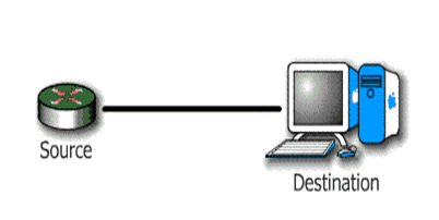
Modem (modulator / demodulator)

Modems convert digital and analog signals. At the source, modems convert digital signals to a form suitable for transmission over analog communication facilities (public telephone lines). At the destination, modems convert the signal back to a digital format.
CSU/DSU (Channel Service Unit / Data Service Unit)
CSUs/DSUs are similar to modems, however they send data in digital format across digital telephone loops. They are usually in a physical box, but they may come in two separate units: CSUs or DSUs.
Multiplexers
A Multiplexer combines multiple signals for transmission over a single circuit. This allows for the transfer of various data simultaneously, such as video, sound, text, etc.

Communication Servers
Communication Servers are typically dial in/out servers that allow users to dial in from remote locations and attach to the LAN.
X.25 / Frame Relay Switches
X.25 and Frame Relay Switches connect private data over public data circuits using digital signal. These units are very similar to ATM switches, but the transfer rate of data is not comparable.
Ethernet
Ethernet was developed by Xerox in 1970. It was implemented through thicknet cable running at 10 Mbps.
Ethernet is a connection media access method that allows all hosts on a network to share the same bandwidth of a link.
Ethernet actually just refers to the LAN implementations that includes three principal categories.
- Ethernet / IEEE 802.3—operates at 10 Mbps on coaxial cable and twisted pair cable.
- 100-Mbps Ethernet—(also known as Fast Ethernet) operates at 100 Mbps over twisted-pair cable.
- 1000-Mbps Ethernet—( also known as Gigabit Ethernet) operates at 1000 Mbps (1 Gbps) over fiber and twisted-pair cables.
| Ethernet and IEEE 802.3 operation involves three basic components: |
| • Transmission • Media access • Collision handling |
Media Accesss
The Ethernet media access uses the following process:
- Any station on a LAN can access the network at any time.
- Before sending data, stations listen for traffic on the network.
- A station waits until it detects no traffic before it transmits data.
Collision handling
Ethernet is a “first come, first serve” environment. In such an environment, any station on the network can transmit whenever the network is quiet. A collision occurs when two stations listen for traffic, hear none, and then transmit data at the same time. Both transmissions are damaged, and the stations must retransmit at a later time.
CSMA / CD

Network Model Overview
In order for a computer to send information to another computer, and for that computer to receive and understand the information, there has to exist a set of rules or standards for this communication process. These standards ensure that varying devices and products can communicate with each other over any network. This set of standards is called a model.
Network Model Advantages
| This division provides advantages for the network design, architecture and implementation. These include: |
| •Reduces complexity – by dividing the processes into groups, or layers, implementation of network architecture is less complex •Provides compatibility – standardized interfaces allow for “plug-and-play” compatibility and multi-vendor integration •Facilitates modularization – developers “swap” out new technologies at each layer keeping the integrity of the network architecture •Accelerates evolution of technology – developers focus on technology at one layer while preventing the changes from affecting another layer •Simplifies learning – processes are broken up into groups divide the complexities into smaller, manageable chunks |
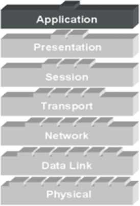
OSI Model
OSI Network Model
There are 7 layers in the OSI model. Each layer is responsible for a particular aspect of data communication. For example, one layer may be responsible for establishing connections between devices, while another layer may be responsible for error checking during transfer.

The layers of the OSI model are divided into two groups: the upper layer and lower layer. The upper layers focus on user applications and how files are represented on the computers prior to transport. For the most part, network engineers are more concerned with the lower layers. It’s the lower layers that concentrate on how the communication across a network actually occurs.
ALL People Seem to Need Data Processing (Layer 7 to 1)
Please Do Not Take Sausage Pizzas Away (Layer 1 to 7)

The Application Layer
The Application Layer is the highest layer in the protocol stack and the layer responsible for introducing data into the OSI stack. In it resides the protocols for user applications that incorporate the components of network applications.
Classification of Applications
- Computer application
- Network applications
- Internetwork applications
Examples: Telnet, FTP, HTTP, WWW Browsers, NFS, SMTP, POP, TFTP

Presentation Layer
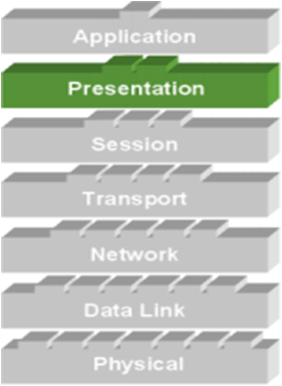
The Presentation Layer manipulates the representation of data for transfer to applications on different devices.
The Presentation Layer is responsible for the following services:
- Data representation
- Data security
- Data compression
Data Representation

Session Layer
The Session Layer establishes, manages, and terminates sessions (different from connections) between applications as they interact on different hosts on a network. Its main job is to coordinate the service requests and responses between different hosts for applications.
Examples: NFS, SQL, RPC, ASP

Three different communication modes exists for data transfer within a session connection: • Single-duplex
Transport Layer
The basic roles of the Transport Layer are to establish end-to-end connections from one computer to another on the network and provide reliable “transport” of data between devices.
Basic Transport Layer Services:
Resource Utilization (multiplexing)
Connection Management (establishing)
Flow Control (Buffering / Windowing)
Reliable Transport (positive acknowledgment / error checking)

Flow Control
Once the connection has occurred and transfer is in progress, congestion of the data flow can occur at a destination for a variety of reasons. Possible options include:
The destination can become overwhelmed if multiple devices are trying to send it data at the same time. It may become overwhelmed if the source is sending faster than it can physically receive.
Congestion Prevention
| The Transport Layer is responsible for providing flow control to alleviate the issue of congestion and provide reliability in the data transfer. Two main methods for flow control include |
| •Buffering •Windowing |
Buffering
Buffering is a form of data flow control regulated by the Transport Layer. It is responsible for ensuring that sufficient buffers are available in the destination for the processing of data and that is data transmitted at a rate that does not exceed what the buffer can handle.

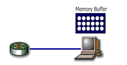
Windowing
Windowing is a flow control scheme in which the source computer will monitor and make adjustments to the amount of information sent based on successful, reliable receipt of data segments by the destination computer. The size of the data transmission, called the “window size”, is negotiated at the time of connection establishment. It is determined by the amount of memory or buffer that is available.

Given a window size of 3, the source (in this case a router) sends 3 data segments to the destination. The destination sends an acknowledgement asking for the next set of data segments.
If the destination does not receive all three of the negotiated data segments, for example, due to a buffer overflow, it sends no acknowledgment. Since the source does not receive an acknowledgment, it knows the data segments should be retransmitted.

Network Layer
The Network Layer is the 3rd layer in the OSI model and is responsible for identifying computers on a network. This layer works closely with layer 2 to translate data packets from a logical address (similar to an IP address) into hardware based MAC addresses.
This layer is concerned with 2 functions: • Routing • Fragmentation / Reassembly

Two types of packets are used at the Network layer:
Data packets: Used to transport user data through the internetwork. Protocols used to support data traffic are called routed protocols. Eg. IP and IPX.
Route update packets: Used to update neighboring routers about the network connected to all routers within the internetwork. Protocols that send route updates are called routing protocols. Eg. RIP, EIGRP, OSPF
Data Link / Physical Layer
LAN and WAN protocols occupy the bottom two layers of the OSI model. These two layers, Physical Layer and Data Link Layer, work very closely together to ensure data transfer across the physical network. Examples: HDLC, Frame Relay, PPP, ATM, FDDI, IEEE 802.3/802.2
To accomplish accurate delivery, the Data Link Layer provides the following services:
1. Machine address determination of both sending and receiving machines
2. Formatting of Network Layer “packets” into frames with machine addresses
attached
3. Sequencing and resequencing of frames transmitted out of sequence
Data Link Sublayers

Logical Link Control (LLC)– responsible for identifying Network layer protocols and encapsulating them.
Media Access Control (MAC)– defines how packets are placed on media
Physical Layer
The Physical Layer is the lowest layer in the OSI model and is concerned with how the physical structure of the network enables transmission of data. It is responsible for defining the mechanical and electrical specifications for the transmission medium within a connection, as well as the transformation or encoding of data into “bits”.
Examples:EIA/TIA-232, V.35, EIA/TIA-449, RJ-45, Ethernet, 802.3
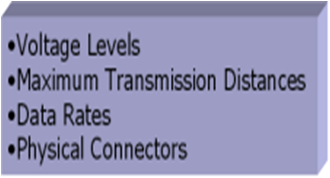
Protocols defined at the Physical Layer standardize physical connections. Specifications include voltage levels, maximum transmission distances, data rates, and physical connectors.
Each layer depends on the service function of the ISO/OSI layer below it. To provide this service, the lower layer uses encapsulation to put the PDU from the upper layer into its data field; then it can add whatever headers and trailers the layer will use to perform its function.
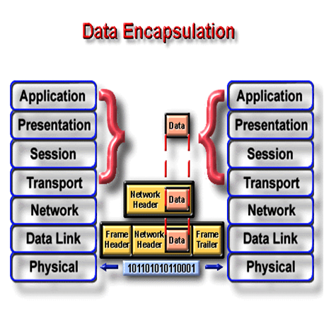
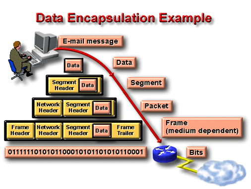
As networks perform services for users, the flow and packaging of the information changes. In this example of internetworking, five conversion steps occur.
What do the 7 layers really do?

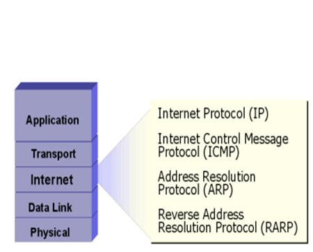
TCP/IP
The Transmission Control Protocol/Internet Protocol (TCP/IP) suite of protocols was developed as part of the research done by the Defense Advanced Research Projects Agency (DARPA).
TCP/IP Protocol Layers
- Process/Application Layer
- Transport Layer or Host-to-Host Layer
- Internet Layer
- Network Access Layer

Application protocols exist for file transfer, e-mail, and remote login. Network management is also supported at the application layer.

Transport services allow users to segment and reassemble several upper-layer applications onto the same transport-layer data stream.
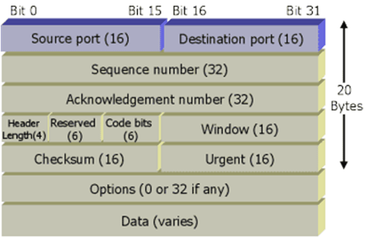
TCP Segment
UDP Segment

IP provides connectionless, best-effort delivery routing of datagrams. It is not concerned with the content of the datagrams. Instead, it looks for a way to move the datagrams to their destination.
Version – Version number (4 bits)
Header Length – Header length in 32-bit words (4 bits)
Priority and Type of Service – How the datagram should be handled. The first 3 bits are priority bits (8 bits).
IP Options – Network testing, debugging, security, and others (0 or 32 bits if any)

ICMP
The Internet Control Message Protocol (ICMP) is implemented by all TCP/IP hosts. ICMP messages are carried in IP datagrams and are used to send error and control messages.
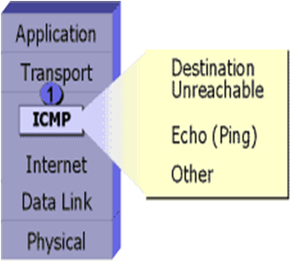
ICMP uses the following types of defined messages:
1. Destination Unreachable
2. Time Exceeded
3. Parameter Problem
4. Subnet Mask Request
5. Redirect
6. Echo
7. Echo Reply
8. Information Request
9. Information Reply
10.Address Request
11.Address Reply
Address Resolution Protocol
Address Resolution Protocol (ARP) is used to resolve or map a known IP address to a MAC sublayer address to allow communication on a multi-access medium such as Ethernet.

The term local ARP is used to describe resolving an address when both the requesting host and the destination host share the same media or wire.
Reverse ARP
Reverse Address Resolution Protocol (RARP) relies on the presence of a RARP server with a table entry or other means to respond to these requests.

ARP and RARP are implemented directly on top of the data link layer.
IP Address
In a TCP/IP environment, end stations communicate seamlessly with servers or other end stations. This communication occurs because each node using the TCP/IP protocol suite has a unique 32-bit logical IP address.
Each IP datagram includes the source IP address and destination IP address that identifies the source and destination network and host.
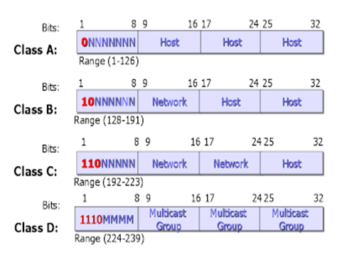
When IP was first developed, there were no classes of addresses. Now, for ease of administration, the IP addresses are broken up into classes.
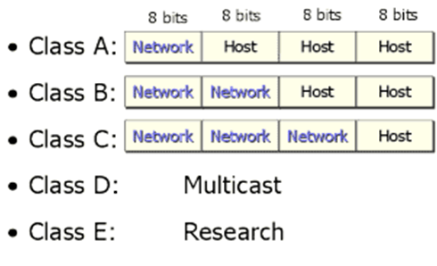
The bits in the first octet identify the address class. The router uses the first bits to identify how many bits it must match to interpret the network portion of the address.

Class A addresses include the following:
- The first bit is 0.
- Range of network numbers: 1.0.0.0 to 126.0.0.0
- Number of possible networks: 127 (1-126 usable, 127 is reserved)
- Number of possible values in the host portion: 16,777,216.
Class B addresses include the following:
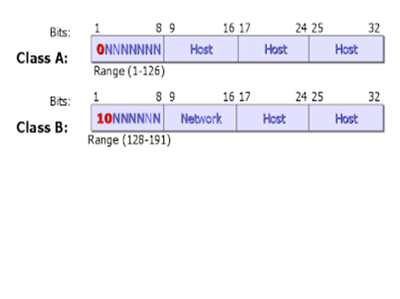
- The first two bits are 10.
- Range of network numbers: 128.0.0.0 to 191.255.0.0
- Number of possible networks: 16,384
- Number of possible values in the host portion: 65,536
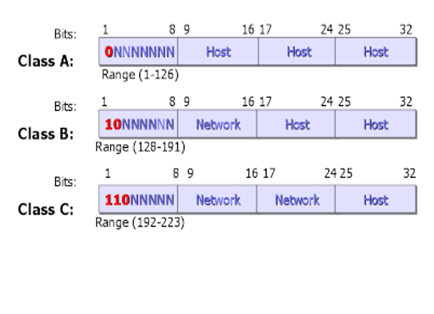
Class C addresses include the following:
- The first three bits are 110.
- Range of network numbers: 192.0.0.0 to 223.255.255.0
- Number of possible networks: 2,097,152
- Number of possible values in the host portion: 256
Class D addresses include the following:
- Range of network numbers: 224.0.0.0 to 239.255.255.255
Routing
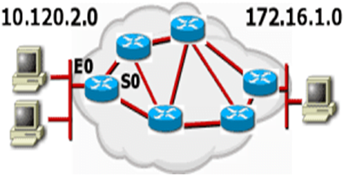
Routing is the process by which an item gets from one location to another. Many items get routed: for example, mail, telephone calls, and trains. In networking, a router is the device used to route traffic.
Key Information a Router Needs
Destination Address – What is the destination (or address) of the item that needs to be routed?
Identifying sources of information – From which source (other routers) can the router learn the paths to given destinations?
Discovering routes – What are the initial possible routes, or paths, to the intended destinations?
Selecting routes – What is the best path to the intended destination?
Maintaining routing information – A way of verifying that the known paths to destinations are the most current.
•Routed protocols – Any network protocol that provides enough information in its network layer address to allow a packet to be forwarded from host to host based on the addressing scheme. Routed protocols define the format and use of the fields within a packet. Packets generally are conveyed from end system to end system. The Internet protocol IP is an example of a routing protocols.
Here are some examples of Routed Protocols:
- Internet Protocol (IP)
- AppleTalk (AT)
- Novell NetWare Protocol
- Xerox Network Systems (XNS)
Routing protocols – Supports a routed protocol by providing mechanisms for sharing routing information. Routing protocol messages move between the routers. A routing protocol allows the routers to communicate with other routers to update and maintain tables. examples of routing protocols are RIP,IGRP,EIGRP and OSPF.
Types of Routing
The different types of routing are:
- Static routing
- Default routing
- Dynamic routing
Static Routing
Routes learned by the router when an administrator manually establishes the route. The administrator must manually update this static route entry whenever an internetwork topology change requires an update.
Benefits:
- There is no overhead on the router CPU.
- There is no bandwidth usage between routers
- It adds security
Disadvantage:
- The administrator must really understand the internetwork and how each router is connected to configure routes correctly.
- If a network is added to internetwork, the administrator has to add a route to it on all routers-by hand
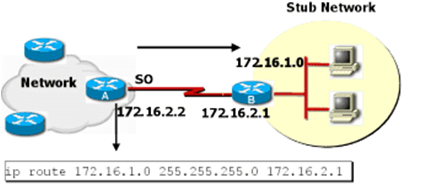
Default Routing
A default route is a special type of static route. A default route is a route to use for situations when the route from a source to a destination is not known or when it is unfeasible for the routing table to store sufficient information about the route.

In the image, Cisco B is configured to forward all frames for which the destination network is not explicitly listed in its routing table to Cisco A.
Dynamic Routing
Routes dynamically learned by the router after an administrator configures a routing protocol that helps determine routes. Unlike static routes, once the network administrator enables dynamic routing, route knowledge is automatically updated by a routing process whenever new topology information is received from the internetwork.

Router Metrics
Routing metrics are used by routing algorithms to determine the desirability of a given route to a destination network. Different routing protocols implement different routing metrics. Routing metrics represent network characteristics. Metric information is stored in routing tables. There are a number of commonly used routing metrics, including:
- Path length
- Reliability
- Delay
- Bandwidth
- Load
- Cost
Hop count is a value that counts the number of intermediate systems (such as
routers) through which a packet must pass to travel from the source to the
destination. The path length is the sum of all the hops in the path.
The reliability routing metric can be based on any of a number of network characteristics. These include: • Bit-error rate (the ratio of received bits that contain errors) • How often each network link fails, and, once down, how quickly each network link can be repaired.
The delay routing metric is based on the length of time required to move a packet from the source to a destination through the internetwork.
Bandwidth
The bandwidth routing metric is based solely on the available traffic capacity of each network link. However, routes through links with greater bandwidth do not necessarily provide better routes than routes through slower links.
Load
The load routing metric is based on the degree to which a network resource (such as a router) is busy. Load is calculated according to such factors as:
- CPU utilization
- Packets processed per second
Cost
The cost routing metric is based on the monetary cost of using each network link. For example, a slower company-owned link can be configured as preferable over faster public links that cost money for usage time.
Routing protocols

Routing protocols are used between routers to determine paths and maintain routing tables. Dynamic routing relies on a routing protocol to disseminate knowledge.
Autonomous Systems
An autonomous system is a collection of networks under a common administrative domain.

Adminstrative Distance
Multiple routing protocols and static routes may be used at the same time. If there are several sources for routing information, an administrative distance value is used to rate the trustworthiness of each routing information source.

An Administrative Distance is a rating of the trustworthiness of a routing information source, such as an individual router or a group of routers. It is an integer from 0 to 255.
| Route Source | Default Distance |
| Connected interface | 0 |
| Static route address | 1 |
| EIGRP | 90 |
| IGRP | 100 |
| OSPF | 110 |
| RIP | 120 |
| External EIGRP | 170 |
| Unknown / Unbelievable | 255 (Will not be |

Distance Vector Protocols
Distance vector routing protocols require routers to periodically send all (or a significant portion) of their routing table in routing updates, but only to neighboring routers.


Routing Loop
Routing loops are, simply, the continuous forwarding of packets due to some fault in a network. Packets are continuously looped throughout a particular network or segment.
What Causes Routing Loops?
Routing loops can occur when routing decisions are based on incorrect information, resulting in packets taking paths that return them to already visited routers. They are created due to a variety of circumstances.
How Do Routers Prevent Loops?
| Routing protocols implement a variety of features designed to prevent routing loops. |
| •Maximum Hop count •Split Horizon •Route Poisoning •Holddowns |
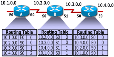
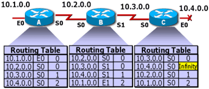
distance vector protocols define infinity as some maximum number. This number refers to a routing metric, such as a hop count.

With this approach, the routing protocols permits the routing loop until the metric exceeds its maximum allowed value. The image shows this defined maximum as 16 hops. Once the metric value exceeds the maximum, network 10.4.0.0 is considered unreachable.
Split Horizon
The rule of split horizon is that it is never useful to send information about a route back in the direction from which the original packet came.

Route Poisoning
With this technique, the router sets a table entry that keeps the network state consistent while other routers gradually converge correctly on the topology change. Used with hold-down timers, which are described soon, route poisoning is a solution to long loops.
Hold-Down

A hold-down timer is a state into which a route is placed so that routers will neither advertise the route nor accept advertisements about the route for a specific length of time (the hold-down period). A route is typically placed in hold down when a link in that route fails.
RIP

RIP, or Routing Information Protocols, is a routing protocols located within IP. There are two versions of RIP supported by Cisco. RIP version 1 and an enhanced version RIPv2, a classless routing protocols.
Characteristics of RIP
- It is a distance vector routing protocols.
- Hop count is used as the metric for path selection.
- The maximum allowable hop count is 15.
- Routing updates are broadcast every 30 seconds by default.
- RIP is capable of load balancing over up to six equal-cost paths (4 paths is the default).
- RIPv1 requires that for each major classful network number being advertised, only one network mask is used per network number. The mask is a fixed-length subnet mask.
- RIPv2 permits variable-length subnet masks on the internetwork. (RIPv1 does not do triggered updates but RIPv2 does do triggered updates.)
Procedure for Configuring RIP
1.Select RIP as the routing protocols using the router rip global configuration command.
Router(config)#router rip
2. Assign a major network number to which the router is directly connected using the network network-number router configuration command.
Router(config-router)#network 10.2.2.0
3.Display network information associated with the entire router using the show ip protocol privileged command.
Router#show ip protocols
4. Display RIP routing updates as they are sent and received using the debug ip rip privileged command.
Router#debug ip rip
IGRP

IGRP is an advanced distance vector routing protocols developed by Cisco in the mid-1980s. IGRP has several features that differentiate it from other distance vector routing protocols, such as RIP.
Characteristics of IGRP
Increased scalability – Improved for routing in larger size networks compared to networks that use RIP.
Sophisticated metric – IGRP uses a composite metric that provides significant route selection flexibility. Internetwork delay and bandwidth by default, and optionally reliability, and load are all factored into the routing decision. IGRP can be used to overcome RIP’s 15-hop limit. IGRP has a default maximum hop count of 100 hops, configurable to a maximum of 255 hops.
Multiple paths – IGRP can maintain up to six nonequal paths between a network source and destination; the paths do not mandate equal costs like with RIP. Multiple paths can be used to increase available bandwidth or for route redundancy.
Procedure for Configuring RIP
- Define IGRP as the IP routing protocols using the router igrp autonomous-system global configuration command.
Router(config)#router igrp 100
2. Assign a major network number to which the router is directly connected using the network network-number router configuration command.
Router(config-router)#network 10.2.2.0
3. Configure load balancing using the variance multiplier router configuration command.
Router(config-router)#variance 1
4. Configure traffic distribution among IGRP load sharing routes using the traffic-share { balanced | min } router configuration command. Router(config-router)#traffic-share balanced
5.Display network information associated with the entire router using the show ip protocol privileged command.
Router#show ip protocols
6. Display the contents of the IP routing table using the show ip route privileged command.
Router#show ip route
Using Telnet to Connect to Remote Devices

Viewing Telnet Connections

Suspending and Resuming a Telnet Session

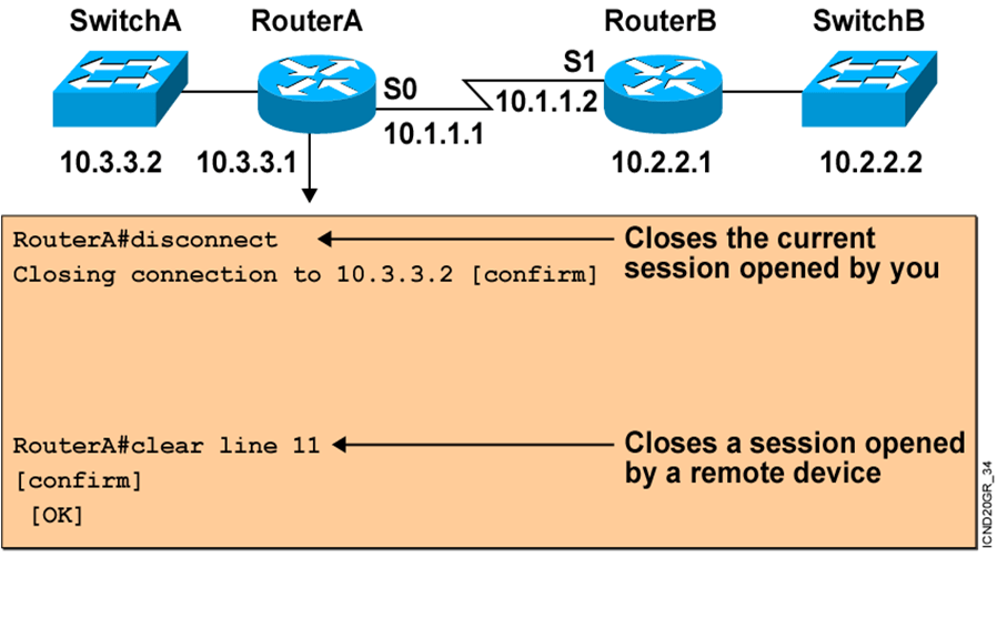
Closing a Telnet Session
Using the ping and trace Commands
Router###ping 10.1.1.10
Type escape sequence to abort.
Sending 5, 100-byte ICMP Echos to 10.1.1.10, timeout is 2 seconds:
!!!!!
Success rate is 100 percent (5/5), round-trip min/avg/max = 4/4/4 ms
Router#trace 192.168.101.101
Type escape sequence to abort.
Tracing the route to 192.168.101.101
1 p1r1 (192.168.1.49) 20 msec 16 msec 16 msec
2 p1r2 (192.168.1.18) 48 msec * 44 msec
Router#


